Joe Touring – Part 3: Suspension
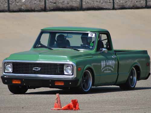
When we started this project the big emphasis was to drive the truck as much as we could, so it makes sense to make it ride smooth, handle well, and sit right using the best parts possible.
In choosing a ’67-’72 Chevrolet C-10 model we already were ahead of the game as they were factory equipped with independent front suspension utilizing a coil spring at each of the corners, while the rear is based on a trailing arm suspension again, utilizing coil springs at each corner. This was a great feat in suspension technology as they hauled a heavy load well, while offering a “car like” ride down the road.
Enter the current age where a ’72 C-10, doesn’t see many heavy work loads anymore, but does get its “fair share” of driving abuse. So keeping with the theme of a driver, we looked to enhance what was given to us from the factory with some modern day upgrades, including raising the front cross-member, moving the front trailing arm mount, kicking up the rear frame four total inches, and relocating all 4 shocks.
Some of these upgrades work “double duty” in the ride and handling department, but we didn’t stop there, as we added new front and rear “anti-sway bars” and a rack and pinion steering system that will allow a more responsive feel to the driver.
Moving some of the components around to different locations also plays a major role as the battery and fuel tank were moved to the rear of the truck to increase traction and better handling by putting the weight where it needs to be.
Let’s take a look at how and what was done in this month’s installment.
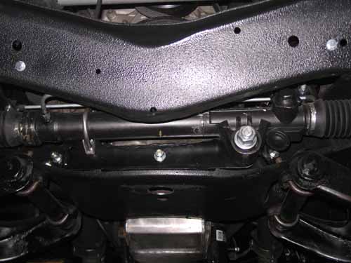
If you’re a C-10 purest, then I apologize for this photo, but if you want your C-10 to handle well then pay attention, because this will be on the final. Seen here is a rack and pinion steering conversion from No Limit Engineering. This cures the plagued and outdated “cross-shaft” steering by removing the stock steering box and linkage arms, which over time wear out causing unresponsive, or “sloppy” steering. Rack and pinion steering uses fewer parts, and is set in true alignment with the spindles offering a more responsive, controlled feel to the driver while maintaining proper geometry.
Ok part two of the quiz. Seen here is a photo of the front cross member that has be “sunk” or “raised” up into the frame-rails an inch and a half. This lowers the center of gravity, for better weight transfer in corners while offering more frame to ground clearance. Also, look closely at the location of the taller stock mount that has also been extended to compensate for the raised crossmember.
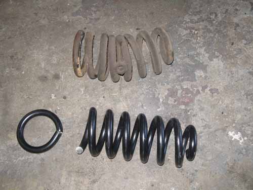
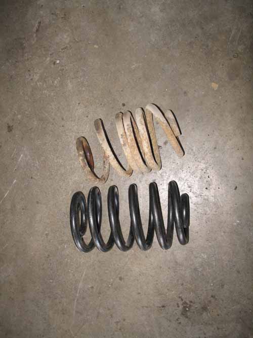
Take a look at those gross factory coil springs! We were due for a new set of coil springs anyways by the looks of what we took out, but get a load of the “coil helpers” that’s not going to help this thing handle through a set of cones, or ride well on the highway. We replaced them with a pair of stock heavy duty half ton coil springs that were modified by cutting a half of a coil off to compensate for the raised cross member.
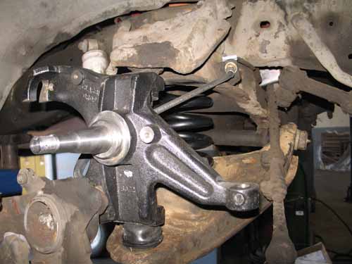
To get the truck to sit right, and improve the steering geometry, we fit a pair of McGaughys 2” drop spindles.
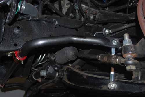
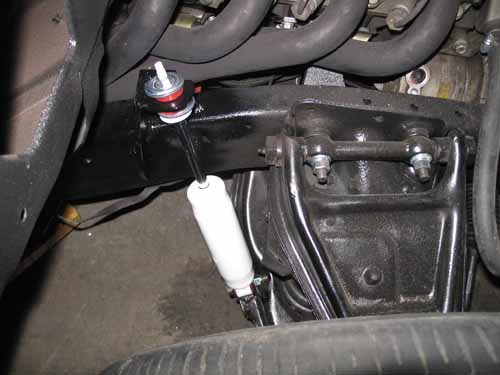
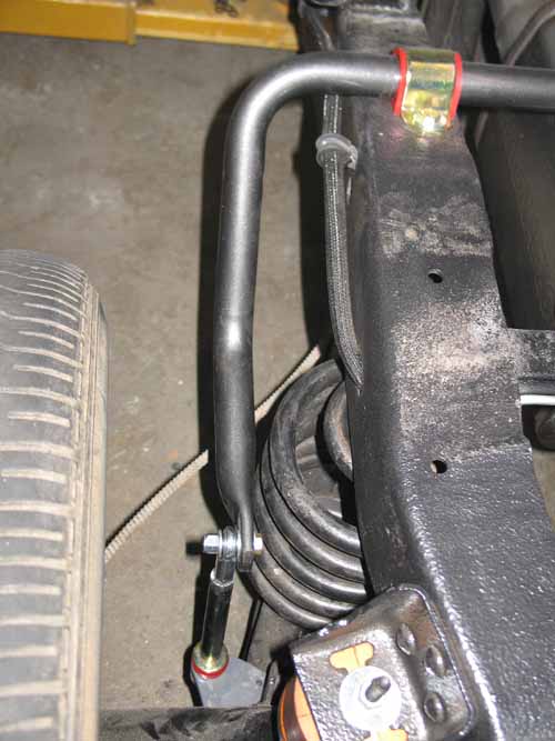
A big and beefy anti-sway bar with adjustable end links was installed to control lateral body roll. The adjustable end links allow the bar to be preloaded if necessary. Other features include zirk fittings on the front mounts that allow you to service the bushings from nasty squeaking.
 |
 |
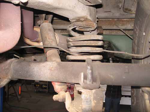
In these two photos, you can see what we started with, an old beat up rear suspension, right? Look closer at where the stock location of the shocks has been placed inside the frame facing inwards. Great for carrying loads, bad for lateral movement. Also you can see that the rear coil springs were in bad shape as well, so a set of coil springs were added to the list.
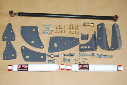
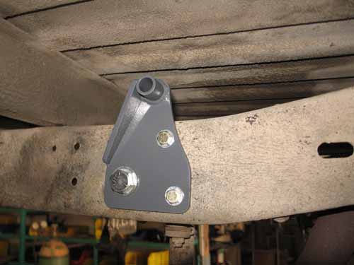
To make the rear of the truck work just as good as the front does, a few items need to be relocated, mainly the shocks and the rear pan-hard bar. Pictured here is No Limit’s kit that relocates the rear shocks out-board of the frame, creating a wider “foot-print” if you will. Next, the stock pan-hard bar will struggle in the position that we want the ride height to sit at, creating a handicap for the lateral weight exchange. No Limit’s kit lowers the attachment point of the bar to the frame and is extended to sit in a neutral or level position where it attaches to the rear differential.
 |
 |
 |
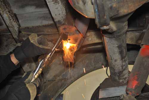
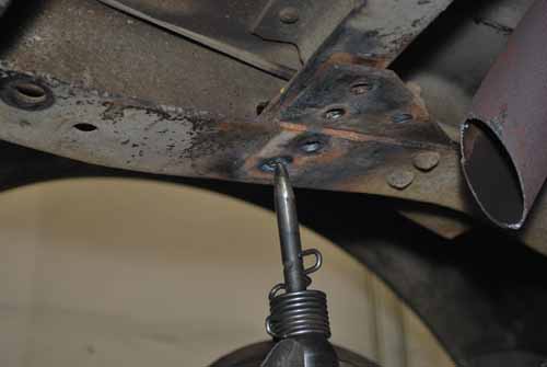
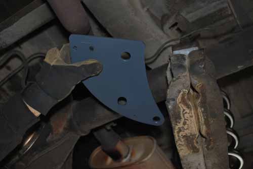
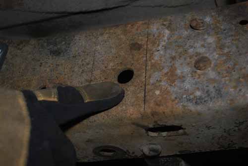
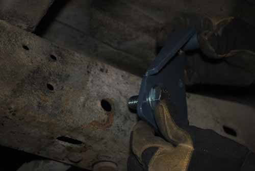
Removal of the stock pan-hard bar mount has begun with a cutting torch. Don’t worry, if you don’t have one a cut-off wheel will work just fine, but will take a while longer to do. After the heads of the rivets are cut off, the stem of the rivets are pushed through with an air chisel. Now that the old mount is gone, the new bracket can be bolted in place, back on the frame.
 |
 |
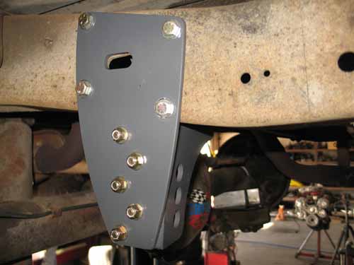 |
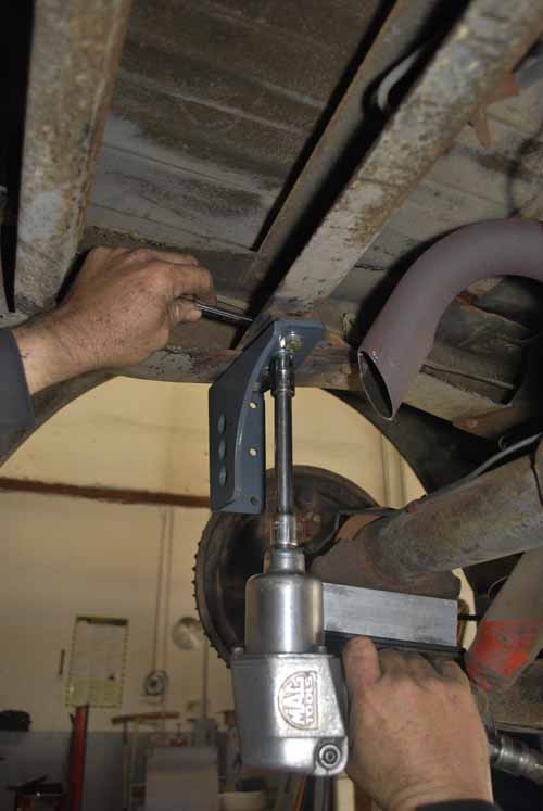
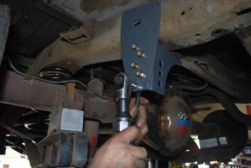
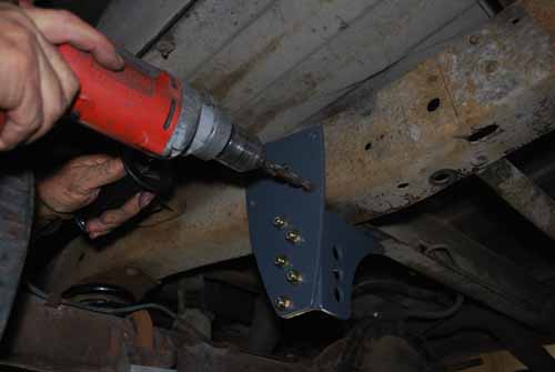
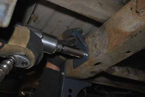
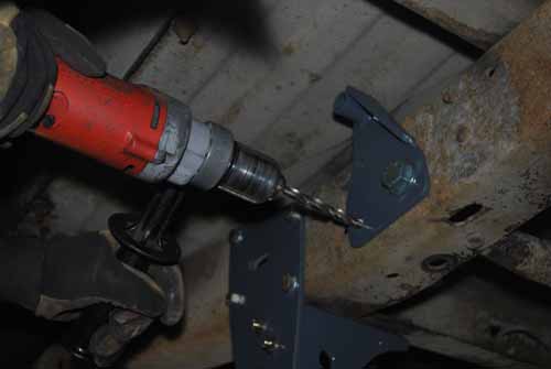
The upper pan-hard bar bracket needs to support force in two directions. So a gusset plate is bolted to the outside of the new bracket, where you’ll need to drill the frame in a few spots to add supporting hardware. Once you get everything drilled and bolted down, it should look something like this.
 |
 |
 |
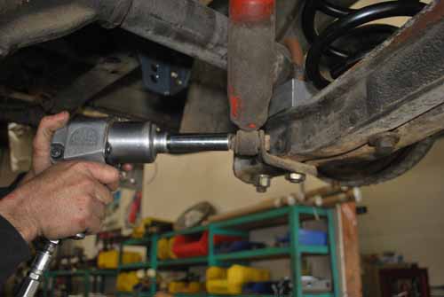
The old shocks are the next things that have to go. The bottom nut is removed first, and then leads into the good ole torch, which makes for great fun in removing objects quite easily.
 |
 |
In order to mount the lower pan-hard par/lower shock mount/rear sway bar mount bracket, the nuts from the U-bolts that hold the axle are removed. Next the axle is lifted from the trailing arms allowing for the bracket to slide into place.
 |
 |
 |
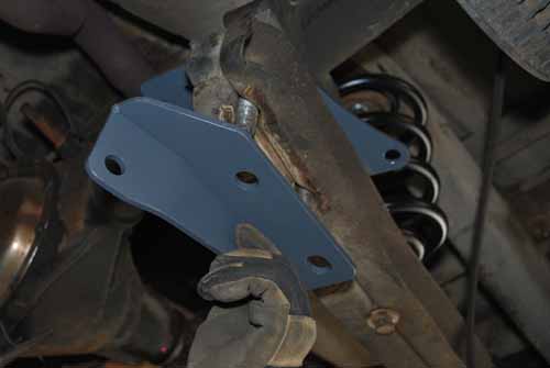
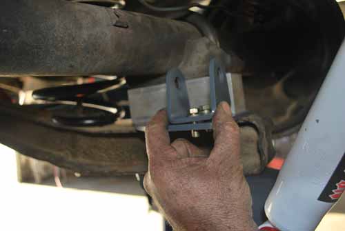
Here’s a close up look at the upper and lower brackets that affix to between the axle and the trailing arms. This combo bracket system isolates lateral forces at the lowest part of the suspension, the trailing arms. This gives the driver a positive feel while cornering, better traction, and a smooth ride.
The lower shock stem is threaded through the lower trailing arm bracket.
 |
 |
 |
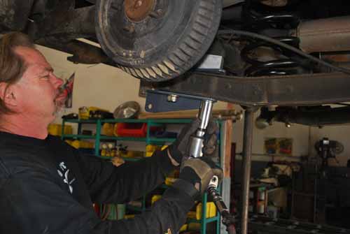
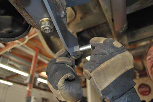
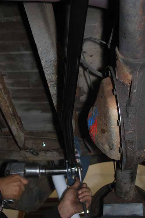
The upper shock bracket is relocated on the outside of the frame, behind the axle, giving the truck more control by stabilizing the weight and reducing wheel hop. What does that all mean? More speed in the corners and better ride on the road. I think that there may be a theme going on here. To install it, just locate the factory hole in the frame and run a bolt and nut to hold the bracket in place.
 |
 |
Next, using the bracket as a guide, drill out the remaining holes and bolt in the hardware that locks it into place.
 |
 |
 |
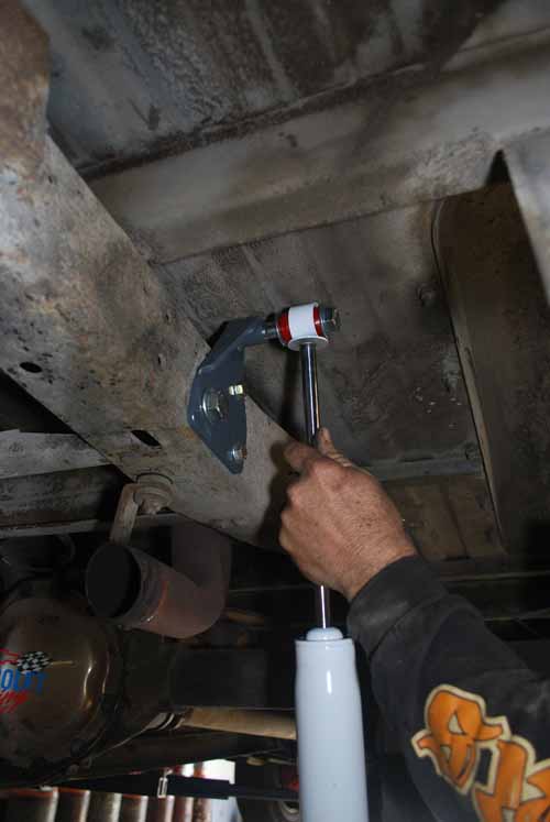
The top shock eyelet is pushed over the shock stem, as the bottom gets the same treatment. Then, using the provided hardware that comes with the kit, the shocks are bolted down tight. Now this C-10’s rear shocks are placed in the right spot to help control side to side movement and have enough travel to curb wheel hop.
 |
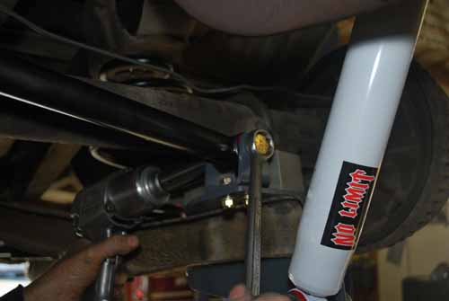 |
Attaching the pan-hard bar at the trailing arm is accomplished by mounting the pan- hard bar bracket to the trailing arm bracket. Then the grade 8 bolt is slid through the bar’s eyelet and is tightened down with a nut.
 |
 |
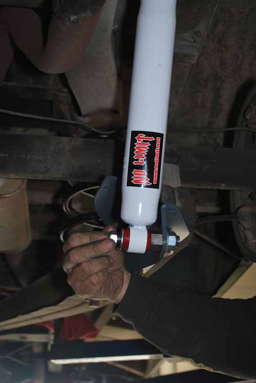
The other end of the pan-hard bar is not only adjustable with the use of a heim joint, or rod end, but the bar itself has been engineered to maintain proper alignment while under a heavy load.
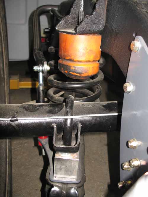
This variable rate bump stop helps soften the blow to the frame when the axle is forced up while traveling over a large dip or speed bump, but it also plays double duty while cornering.
 |
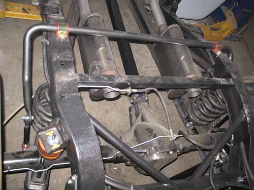 |
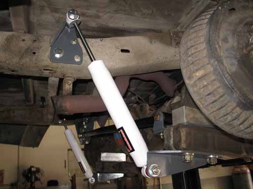
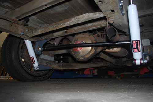
In this group of photos, you can get a great look of how No Limit’s rear anti-sway bar mounts over the frame, and down to the lower trailing arm brackets. A design like this paired with the lower pan-hard bar triangulates lateral forces that slows weight transfer giving the driver more control.
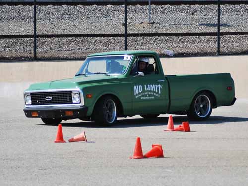
So how does it work? No Limit is no stranger to the autocross track and they have the time slips to prove it.
Sources: No Limit Engineering: www.nolimit.net McGaughys Suspension: www.mcgaughys.com
Sources:
No Limit Engineering: www.nolimit.net
SEM “rock-it liner” www.semproducts.com
Coast Airbrush: www.coastairbrush.com
Chevy Truck Salvage: (714) 554-1850